Followers

Tuesday 14 December 2010

The components of a computer system and their functions. Part II

PORTS


Most printers use a special connector called a parallel port. Parallel port carry data on more than one wire, as opposed to the serial port, which uses only one wire. Parallel ports use a 25-pin female DB connector. Parallel ports are directly supported by the motherboard through a direct connection or through a dongle. A parallel port is a type of interface found on computers (personal and otherwise) for connecting various peripherals. In computing, a parallel port is a parallel communication physical interface. It is also known as a printer port or Centronics port. The parallel port is part of the input/output panel, the input/output panel is the panel at the back of the desktop and surrounds the sides of a laptop. The input/output panel consists of a parallel port, 2 serial ports, a ps/2 keyboard and mouse connector, universal serial bus (USB) ports, ethernet port, audio and microphone ports and a midi port.


CPU


The central processing unit, also called the microprocessor performs all the calculations that take place inside a pc. CPUs come in Variety of shapes and sizes. Modern CPUs generate a lot of heat and thus require a cooling fan or heat sink. The cooling device (such as a cooling fan) is removable, although some CPU manufactures sell the CPU with a fan permanently attached.


The central processing unit (CPU) is the portion of a computer system that carries out the instructions of a computer program, and is the primary element carrying out the computer's functions. Pronounced as separate letters it is the abbreviation for central processing unit. The CPU is the brains of the computer. Sometimes referred to simply as the central processor, but more commonly called processor, the CPU is where most calculations take place. In terms of computing power, the CPU is the most important element of a computer system.
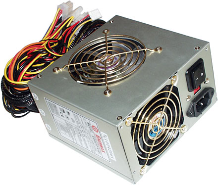
The power supply, also called a power supply unit or PSU, is the component that supplies power to a computer. Most personal computers can be plugged into standard electrical outlets. The power supply then pulls the required amount of electricity and converts the AC current to DC current. It also regulates the voltage to eliminate spikes and surges common in most electrical systems. Not all power supplies, however, do an adequate voltage-regulation job, so a computer is always susceptible to large voltage fluctuations.
Power supplies are rated in terms of the number of watts they generate. The more powerful the computer, the more watts it can provide to components.


CABLES


AT power connectors

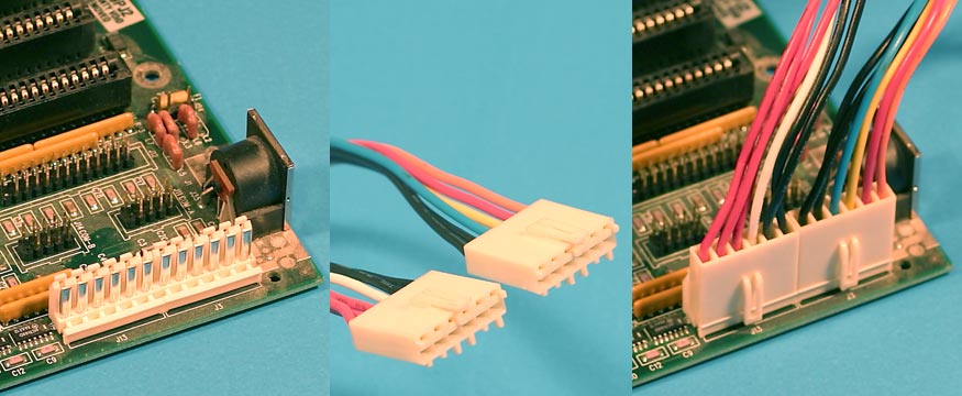
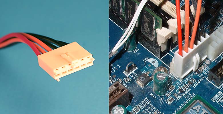
The original PC debuted in 1981 and used two cables to connect the PSU (power supply) to the motherboard. The two cables plug side by side into the motherboard connectors. Sometimes they are keyed so they only plug in one way and sometimes they aren't. Even if they're keyed you can insert them the wrong way if you put a little effort into it. You always have to remember to plug them in so the black wires are next to each other. It's either "black to black" or smoke and a shower of sparks.
Peripheral Power Connectors
The four pin peripheral power cable dates back to the original PC. It was used for floppy drives and hard disks. It's still around and is now also used for all kinds of things including add-on fans, extra video card power, supplemental motherboard power, and case lighting. It's as old as the hills but is still very widely used. The connector is shaped so that it only fits in one way. You don't have to worry about inserting it the wrong way. People often use the term "4 pin Molex power cable" or "4 pin Molex" to refer to a four pin peripheral power cable. It's not a technically useful term because the 4 pin 12 volt cable is also a 4 pin Molex cable (Molex makes lots of connectors) but "4 pin Molex" is commonly used to refer to peripheral cables anyway.
Floppy Power Connectors
The four pin floppy drive cable showed up when PCs started including 3.5 inch floppy drives. This kind of cable is also sometimes used as an auxiliary power cable for AGP video cards which use more power than can be drawn from the motherboard slot. The connector is shaped so that it only fits in one way so you don't have to worry about inserting it the wrong way. Floppy cables are built with small connectors and 20 awg (American Wire Gauge) wire so they are limited to relatively low current uses.
6 Pin ATX auxiliary power connector
The aux power cable was added to provide extra wattage to motherboards for 3.3 and 5 volts. This connector is rarely used anymore. It's most commonly found on older dual CPU AMD motherboards. You're more likely to sight Bigfoot than a motherboard which uses this connector. It plugs into the 6 pin version of the motherboard connector used by the original PC main power cables.


SATA Connector
SATA was introduced to upgrade the ATA interface (also called IDE) to a more advanced design. SATA includes both a data cable and a power cable. The power cable replaces the old 4 pin peripheral cable and adds support for 3.3 volts (if fully implemented). The connector is shaped so it can only be plugged in the correct way.


20 Pin ATX Main Power Connector
In 1996 PC makers started switching to the ATX standard which defined a new 20 pin motherboard power connector. It includes a 3.3 volt rail which is used to power newer chips which require a lower voltage than 5 volts. It also has a standby 5 volt rail which is always on even when the power supply is turned off to provide standby power to the motherboard when the machine is sleeping. The new connector also allows the motherboard to turn the power supply on and off rather than depend on the user to flip a power switch. This connector is polarized so it can only be plugged in pointing in the correct direction.


24 Pin ATX Main Power Connector
The 24 pin main power connector was added in ATX12V 2.0 to provide extra power needed by PCI Express slots. The older 20 pin main power cable only has one 12 volt line. The new 24 pin connector added one line apiece for ground, 3.3, 5, and 12 volts. The extra pins made the auxiliary power cable unnecessary so most ATX12V 2.x power supplies don't have them. The 24 pin connector is polarized so it can only be plugged in pointing in the correct direction.


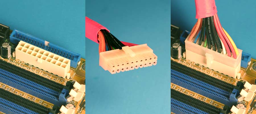
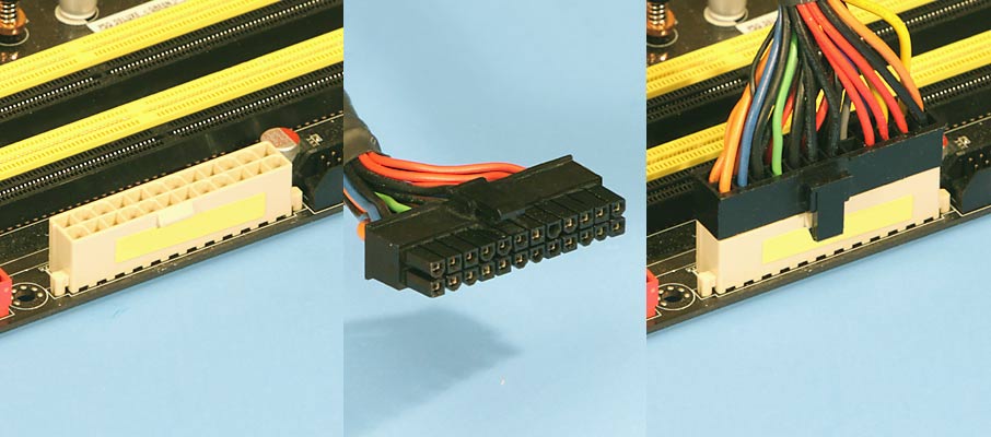
Motherboards can come with either a 20 pin main power connector or a 24 pin main power connector. Many power supplies come with a 20+4 cable which is compatible with both 20 and 24 pin motherboards. A 20+4 power cable has two pieces: a 20 pin piece, and a 4 pin piece. If you leave the two pieces separate then you can plug the 20 pin piece into a 20 pin motherboard and leave the 4 pin piece unplugged. Be sure to leave the 4 pin piece unplugged even if it fits into another connector. The 4 pin piece is not compatible with any other connectors. If you plug the two pieces of a 20+4 power cable together then you have a 24 pin power cable which can be plugged into a 24 pin motherboard.


4 Pin ATX 12 Volt Connector
Older computers put most of their load on 3.3 and 5 volts. As time passed, computers drew more and more of their load from 12 volts. Before this power cable was introduced there was just one 12 volt line provided to the motherboard. This cable added two more 12 volt lines so more of the load could be shifted to 12 volts. The power coming from this connector is usually used to power the CPU but some motherboards use it for other things as well. The presence of this connector on a motherboard means it's an ATX12V motherboard. For dual 12 volt rail power supplies, this connector provides the voltage refered to as 12V2. The power cable which plugs into the 4 pin connector has two black wires and two yellow wires. This cable is sometimes called an "ATX12V" cable or "P4" cable although neither of those are technically accurate descriptions.  If you have one of these connectors on a motherboard then you must plug a power cable into it or your CPU won't get any power. The one exception is that when this connector was new, some motherboards shipped with a socket into which you could plug a 4 pin peripheral power cable as an alternative. That helped people who had older power supplies which didn't have the 4 pin 12 volt cable.
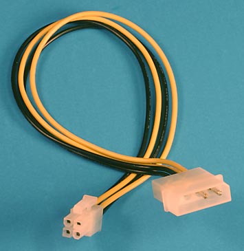
The 4 pin 12 volt cable is polarized so it can only be plugged into the 4 pin motherboard connector correctly. If you look carefully at the picture above you can see that two of the pins are square and the other two have rounded corners. The motherboard connectors also have the same square and rounded arrangement so the power cable only fits in one way. At least that's true unless you try really hard to force it into the connector. With enough force you can sometimes get a cable with a small number of pins into a connector which doesn't match. If you look carefully you can also see that the square and rounded pattern matches various positions on other motherboard connectors like the 20 pin main power connector and 24 pin main power connector. Do yourself a favor and only plug the 4 pin 12 volt cable into the motherboard connector where it belongs (unless you enjoy smoke and fried components).
Peripheral To 4 Pin ATX 12 Volt Connector Adapter
If your power supply doesn't have a 4 pin 12 V cable then you can provide one with the adapter shown above. It converts a 4 pin peripheral cable into a 4 pin 12 V cable.


8 Pin EPS +12 Volt Connector
This cable was originally created for workstations to provide 12 volts to power multiple CPUs. But as time has passed many CPUs require more 12 volt power and the 8 pin 12 volt cable is often used instead of a 4 pin 12 volt cable. Depending on the power supply, the connector may contain one 12 volt rail in all 8 pins or two 12 volt rails taking up 4 pins apiece. It is often refered to as an "EPS12V" cable.
The 8 pin 12 volt cable is polarized so it can only be plugged into the 8 pin motherboard connector correctly. If you look carefully at the picture above you can see that four of the pins are square and the other four have rounded corners. The motherboard connectors also have the same square and rounded arrangement so the power cable only fits in one way. At least that's true unless you try really hard to force it into the connector. With enough force you can sometimes get a cable with a small number of pins into a connector which doesn't match. The 8 pin cable has enough pins that it's pretty hard to insert it in the wrong direction but determined people might be able to do it. If you look carefully you can also see that the square and rounded pattern matches various positions on other motherboard connectors like the 20 pin main power connector and 24 pin main power connector. You should only plug the 8 pin 12 volt cable into the motherboard connector where it belongs unless you enjoy the smell of fried electronics.
You can also plug an 8 pin 12 volt cable into a 4 pin 12 volt motherboard connector. Four of the pins on the 8 pin cable fit into the motherboard connector and the other four pins hang off the end. The 8 pin cable only fits into one end of the 4 pin motherboard connector unless you try hard to force it into the wrong position. The 8 pin cable is electrically compatible but it may not fit into a 4 pin motherboard. There is often a component which blocks the area where the 4 pins would hang off the end. And sometimes the plastic end of the 4 pin connector is too thick to fit between the pins of the 8 pin cable.
Make sure that you don't try to plug an 8 pin 12 volt cable into the 8 Pin PCI Express power connector on a video card. The two cables look very similar so it's easy to get the two confused. 8 Pin PCI Express power cables are usually labeled to distinguish them from 8 pin 12 volt cables. The PCI Express cable usually has "PCI-E" printed on the connector. If there are no labels then you can usually use wire colors to tell the two kinds of cables apart. An 8 pin 12 volt cable has yellow wires on the same side as the connector clip. An 8 Pin PCI Express cable has black wires on the clip side. The two power cables are also keyed differently so you can't plug one kind of power cable into the other kind of connector. But as with this kind of connector, you can sometimes force the wrong kind of cable into a connector if you push hard enough. Make sure you have the right kind of cable before plugging it in. The two are definitely not compatible with each other.
On large machines, CPUs require one or more printed circuit boards. On personal computers and small workstations, the CPU is housed in a single chip called a microprocessor. Since the 1970's the microprocessor class of CPUs has almost completely overtaken all other CPU implementations.
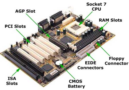
The CPU itself is an internal component of the computer. Modern CPUs are small and square and contain multiple metallic connectors or pins on the underside. The CPU is inserted directly into a CPU socket, pin side down, on the motherboard. Each motherboard will support only a specific type or range of CPU so you must check the motherboard manufacturer's specifications before attempting to replace or upgrade a CPU. Modern CPUs also have an attached heat sink and small fan that go directly on top of the CPU to help dissipate heat.
Two typical components of a CPU are the following:
  • The arithmetic logic unit (ALU), which performs arithmetic and logical operations.
  • The control unit (CU), which extracts instructions from memory and decodes and executes them, calling on the ALU when necessary.
 The central processing unit carries out each instruction of the program in sequence, to perform the basic arithmetical, logical, and input/output operations of the system. This term has been in use in the computer industry at least since the early 1960s. The form, design and implementation of CPUs have changed dramatically since the earliest examples, but their fundamental operation remains much the same. Early CPUs were custom-designed as a part of a larger, sometimes one-of-a-kind, computer. However, this costly method of designing custom CPUs for a particular application has largely given way to the development of mass-produced processors that are made for one or many purposes. This standardization trend generally began in the era of discrete transistor mainframes and minicomputers and has rapidly accelerated with the popularization of the integrated circuit(IC). The IC has allowed increasingly complex CPUs to be designed and manufactured to tolerances on the order of nanometers. Both the miniaturization and standardization of CPUs have increased the presence of these digital devices in modern life far beyond the limited application of dedicated computing machines. Modern microprocessors appear in everything from automobiles to cell phones and children's toys.


RAM
Random-Access Memory (RAM) stores programs and data currently being used by the CPU. RAM is measured in units called bytes. RAM has been packaged in many different ways. The most current package is called a 168-pin DIMM (Dual Inline Memory module).
Random-access memory (RAM) is a form of computer data storage. Today, it takes the form of integrated circuits that allow stored data to be accessed in any order (i.e., at random). "Random" refers to the idea that any piece of data can be returned in a constant time, regardless of its physical location and whether it is related to the previous piece of data.
The word "RAM" is often associated with volatile types of memory (such as DRAM memory modules), where the information is lost after the power is switched off. Many other types of memory are RAM as well, including most types of ROM and a type of flash memory called NOR-Flash. Pronounced "ramm", acronym for random access memory, a type of computer memory that can be accessed randomly; that is, any byte of memory can be accessed without touching the preceding bytes. RAM is the most common type of memory found in computers and other devices, such as printers.

There are two different types of RAM: DRAM (Dynamic Random Access Memory) and SRAM (Static Random Access Memory). The two types differ in the technology they use to hold data, with DRAM being the more common type. In terms of speed, SRAM is faster. DRAM needs to be refreshed thousands of times per second while SRAM does not need to be refreshed, which is what makes it faster than DRAM. DRAM supports access times of about 60 nanoseconds, SRAM can give access times as low as 10 nanoseconds. Despite SRAM being faster, it's not as commonly used as DRAM because it's so much more expensive. Both types of RAM are volatile, meaning that they lose their contents when the power is turned off.
In common usage, the term RAM is synonymous with main memory, the memory available to programs. For example, a computer with 8MB RAM has approximately 8 million bytes of memory that programs can use. In contrast, ROM (read-only memory) refers to special memory used to store programs that boot the computer and perform diagnostics. Most personal computers have a small amount of ROM (a few thousand bytes). In fact, both types of memory (ROM and RAM) allow random access. To be precise, therefore, RAM should be referred to as read/write RAM and ROM as read-only RAM.

The components of a computer system and their functions.

A computer is made up of many components that may seem daunting to many people that do not have a basic knowledge. I aim to help those less fortunate and give them a knowledge of the computer components, their fuctions and how they fit together on a mother board. I hope this is of some use to you.


MOTHERBOARD

The main reason for a motherboard is to connect everything together easily and is easy to access. It is located in the case normally attached parrallel to the inside of the case. It is normally connected to everything via wires, ribbons and connectors. However many of the main things are connected directly onto the motherboard itself.


Firstly, there are two types of motherboards, AT motherboard, and ATX motherboard. AT stands for advanced technology and  ATX means advanced technology extended. AT motherboards are older, and not commonly used now a days and ATX is the newer more advanced model replacing the AT version. The AT and ATX motherboards differ in the form factor. The form factor specifies the physical dimensions of major system components. The "form factor" for the "Full" AT is 12" wide x 13.8" deep, and the "Baby" AT is 8.57" wide x 13.04" deep. The "Full" ATX is 12" wide x 9.6" deep and the "Mini" ATX is 11.2" wide x 8.2" deep. Other major differences include power supply connectors, and keyboard connectors.


There are two basic differences between AT and ATX power supplies. The connectors that provide power to the motherboard, and the "soft switch". On older AT power supplies, the Power-on switch wire from the front of the computer is connected directly to the power supply. On newer ATX power supplies, the power switch on the front of the computer goes to the motherboard over a connector labeled something like; "PS ON", "Power SW", "SW Power", etc. This allows other hardware and/or software to turn the system on and off. The motherboard controls the power supply through pin #14 of the 20 pin connector or #16 of the 24 pin connector on the motherboard. This pin carries 5V when the power supply is in standby. It can be grounded to turn the power supply on without having to turn on the rest of the components. This is useful for testing or to use the computer ATX power supply for other purposes.


The AT keyboard was a keyboard with 84 keys introduced with the IBM PC/AT computer. It succeeded the 83-key PC/XT keyboard and therefore did not have many of the features seen on modern keyboards such as arrow keys and dual ctrl and alt keys. It was later replaced with the 101-key Enhanced keyboard. Nonetheless, "AT keyboard" remains a popular name for any keyboard that uses the 5-pin DIN connector. This connector is often considered a Legacy port. Many Enhanced keyboards used this, though it was eventually superseded by the PS/2 connector and many modern computers use Universal Serial Bus (USB) connectors instead. Compared to the 83-key XT keyboard, the AT keyboard uses a different communication protocol and a different set of scancodes. Despite having the same connector, the two are not interchangeable.


STORAGE DEVICES


A data storage device is a device for recording and storing information and data. Storing data can be done using any form of energy, these forms of energy span from manual muscle power in handwriting, to acoustic vibrations in phonographic recording or to electromagnetic energy modulating magnetic tape and optical discs. A storage device may hold information and/or process information. A device that only holds information is a recording medium. Devices that process information (data storage equipment) may either access a separate portable (removable) recording medium or a permanent component to store and retrieve information.


Electronic data storage is storage which requires electrical power to store and retrieve that data. Electromagnetic data may be stored in either an analog or digital format on a variety of media. This type of data is considered to be electronically encoded data, whether or not it is electronically stored in a semiconductor device, for it is certain that a semiconductor device was used to record it on its medium.
Most electronically processed data storage media (including some forms of computer data storage) are considered permanent (non-volatile) storage, that is, the data will remain stored when power is removed from the device. In contrast, most electronically stored information within most types of semiconductor (computer chips) microcircuits are volatile memory (it vanishes if power is removed). With the exception of barcodes and OCR data, electronic data storage is easier to revise and may be more cost effective than alternative methods due to smaller physical space requirements and the ease of replacing (rewriting) data on the same medium. However, the durability of methods such as printed data is still superior to that of most electronic storage media. The durability limitations may be overcome with the ease of duplicating (backing-up) electronic data.


BIOS


Bios stands for Basic Input Output Systems. The BIOS software is built into the PC, and is the first code run by a PC when powered on ('boot firmware'). The primary function of the BIOS is to load and start an operating system. When the PC starts up, the first job for the BIOS is to initialize and identify system devices such as the video display card, keyboard and mouse, hard disk, CD/DVD drive and other hardware. The BIOS then locates software held on a peripheral device (designated as a 'boot device'), such as a hard disk or a CD, and loads and executes that software, giving it control of the PC. You can change the bios settings by entering the screen that looks like this:
File:AwardBIOS CMOS Setup Utility.png


EXPANSION SLOTS


A video card, video adapter, graphics accelerator card, display adapter, or graphics card is an expansion card whose function is to generate output images to a display. Many video cards offer added functions, such as accelerated rendering of 3D scenes and 2D graphics, video capture, TV-tuner adapter, MPEG-2/MPEG-4 decoding, FireWire, light pen, TV output, or the ability to connect multiple monitors (multi-monitor). Other modern high performance video cards are used for more graphically demanding purposes, such as PC games.


CMOS BATTERY


On the mother board there is a thing called the CMOS battery. Short for complementary metal oxide semiconductor. Pronounced "see-moss", CMOS is a widely used type of semiconductor. CMOS semiconductors use both NMOS (negative polarity) and PMOS (positive polarity) circuits. Since only one of the circuit types is on at any given time, CMOS chips require less power than chips using just one type of transistor. This makes them particularly attractive for use in battery-powered devices, such as portable computers. Personal computers also contain a small amount of battery-powered CMOS memory to hold the date, time, and system setup parameters. 
continues in next post.....


HOW TO REPLACE AN EXPANSION CARD

Here are some easy to follow steps to remove your graphics card. you will need:
  • An anti-static wrist strap
  • An electrical screwdriver or a ordinary screwdriver
  • Graphics Card
1 Static electricity can seriously damage the components inside a computer. To avoid this you must ensure you are grounded when operating inside your computer. One way to do this is to purchase an anti-static wrist strap which you should wear at all times. The wrist-strap plugs into an electrical socket which will automatically discharge the static electricity in your body. Also you may need to put the compnents into seperate ESD (ElectroStatic Discharge) bags.

2 To get into the tower you will have to remove the panel which is on the right hand side when viewing the tower from the back. Open this side of computer case by removing the screws at the back of the tower which are holding it in place. Then simply slide the panel off.

 
3 Locate the old card on the motherboard and remove it by firmly lifting it out of the slot it occupies. Insert the new card, ensuring it is firmly pushed into the slot. Note: Some AGP ports have sliding locks that hold graphics cards in place. If your card is reluctant to come out or won't stay in, check if your port has these. If it does, use a screwdriver or your fingers to pull it to the right (open) or left (close). Make sure it clicks before removing or adding the card to minimize the risk of damaging the new card or your motherboard.

4 Replace the tower's side panel, switch the computer on and install appropriate software that came with the new card.